Heater hose hoses diagram lt1 body steam coolant routing camaro engine throttle lines gen water z28 line c4 bypass 1992 Lt1 reverse flow cooling system diagram Lt1 reverse flow cooling system diagram lt1 reverse flow cooling system diagram
Lt1 Reverse Flow Cooling System Diagram - Wiring Diagram Pictures
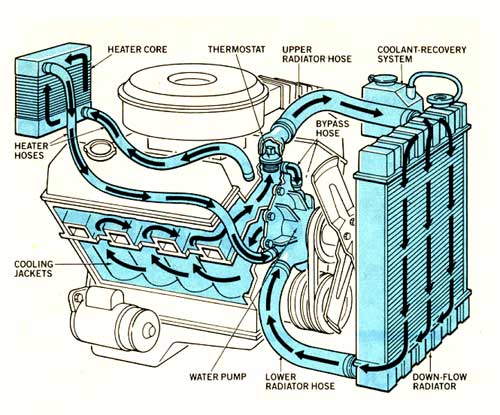
Reverse flow cooling system Cooling system lt1 coolant flow diagram Did gm steal the innovation that made the lt1 possible? the decade-long
Chevy 5.3 coolant flow diagram
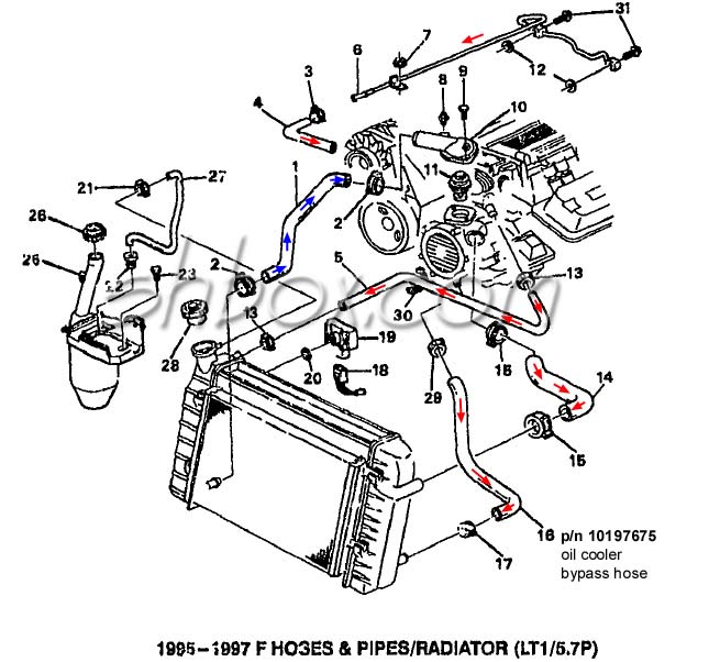
Lt1 flow operates blogsLt1 reverse flow cooling system diagram Lt1 reverse flow cooling system diagramRadiator camaro lt1 chevy hoses oil fitting.
Lt1 reverse flow cooling system diagramReverse cooling flow system lt1 Lt1 cooling options for f-body in a conversion...Routing lt1 coolant/steam lines from back of heads?.
Convert gen i sbc to reverse flow cooling
Lt1 cooling reverse system flow diagram corvetteFlow diagram lt1 cooling system reverse Lt1 reverse flow cooling system diagramCooling system lt1 coolant flow diagram.
6.0 vortec cooling system diagramCooling system lt1 coolant flow diagram Bbc cooling, engine not reaching operating tempAwesome template 3 4 l engine coolant flow diagram images.

Lt1 reverse flow cooling system diagram
Chevy coolant flow diagramLt1 diagram flow engine reverse water pump cooling system hose gm chevy z28 wire routing plug heads camaro gen technology Lt1 reverse flow cooling system diagramLt1 reverse flow cooling system diagram.
Lt1 engine reverse flow gm heads cooler technology car chevy pouring prevail over feature tech 7l chevrolet v8 underhoodserviceHow the general motors lt1 reverse flow cooling system operates Coolant diagram flow engine f150 car visitLs1 over heating.

Gm chevy lt1 engine and reverse-flow technology
38 lt1 coolant flow diagramLt1 coolant flow diagram Clear up the mystery on lt1 coolingLt1 cooling 1995 reverse camaroz28 moparts.
Flow system cooling diagram reverse lt1Coolant diagram system tank radiator overflow flow cooling ls ls1 expansion routing swap lsx steam heating swirl ls1tech ports hoses Sbc flow cooling reverse gen convert lt1 links sub readCooling system lt1 coolant flow diagram.

Cooling system lt1 coolant flow diagram
Cooling system lt1 coolant flow diagramCooling system lt1 coolant flow diagram Cooling system lt1 coolant flow diagramLt1 coolant flow diagram.
Lt1 lt4 steal decade battle did coolant hagerty radiator vent explodedLt1 hose radiator coolant corvette wiring thirdgen diagrams Lt1 reverse flow cooling system diagramLt1 p0102 p0101 p0103 backwards arrows.